If you've used Siemens' older Sizer software to size drives and motors, you may not realize it's been fully phased out. Everything Sizer did and more is now built directly into the TIA Selection Tool, a free software with free updates that covers the full range of current Siemens hardware, including the newest drives coming to market.
The interface has changed significantly, and the updated workflow is genuinely faster once you know where to look. Here's a complete walkthrough of how to size a single-axis S210 servo system from scratch.
Starting Point: Project View vs. Portal View
When you open TIA Selection Tool, it defaults to Portal View. For day-to-day sizing work, Project View is where you want to be. Toggle between the two using the button in the bottom left of the project window. Once in Project View, you'll see your project tree on the left and a work window in the center — this is where everything happens.
Every device you add will have a Properties window showing the group name, editor name, application notes, and timestamps for creation and changes. Useful when managing multiple projects or handing work off to a colleague.
1. Add a New Device
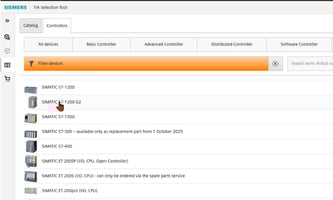
Add a new device by double-clicking in the project window or using the toolbar. You'll see options for controllers, I/O systems, HMI panels, and drive technology. Select Drive Technology, then choose Drive Dimensioning with Sizer Integrated in TIA Selection Tool.
Once added, an undefined axis appears in your project tree. That's expected — it just means you haven't configured it yet.
2. Define your Portfolio Selection
The Portfolio tab is where you narrow down hardware options. As you fill in requirements, the tool filters compatible motors and drives in real time. Hover over any motor in the results list and it highlights the corresponding compatible drives — and vice versa.
Work through these fields:

3. Define your Mechanical System
Click Add Load and choose your mechanical system type — belt drives, rack and pinion, rotary table, and others are available. For this example, select Ball Screw Actuator, then click Configure.
The orange-highlighted fields are the only required inputs to fully define the mechanical model:
| Parameter | Value used in this example |
|---|---|
| Steady Payload | 20 kg |
| Ball Screw Diameter | 10 mm |
| Ball Screw Length | 1,000 mm |
| Ball Screw Density | Steel (use material lookup table — density auto-populates) |
| Lead Screw Pitch | 3 mm |
Once that final value is entered, the hazard symbol in the project tree turns into a green checkmark. Mechanical system: defined.
4. Build your Motion Profile
The Motion Profile tab is where you define how the axis actually moves. The tool's pin system lets you choose which three variables to define — the rest are calculated automatically. A practical approach: pin travel distance, move time, and motion type.
For motion type, trapezoidal is the standard choice for most applications — constant acceleration to the designated speed, hold, then decelerate to stop. Set units to millimeters, then enter:
| Parameter | Value |
|---|---|
| Travel Distance | 500 mm |
| Move Time | 10 seconds |
| Maximum Velocity (Vmax) | 75 mm/s |
| Pause Time (t pause) | 2 seconds |
That defines the forward move. For a full cycle, copy the forward move (Ctrl+C, Ctrl+V) and flip the direction toggle — no need to re-enter all the values. The nth move placeholder that appears at the end is normal; the tool only evaluates the moves you've defined.
5. Select your Motor
Click on Motor in the project tree. Available motors are filtered to your load requirements, showing required torque, average speed, required power, and effective power. For this load — 20 kg on a 10mm ball screw with 3mm pitch — torque and speed requirements are modest. A SIMOTICS S-1FT2 is a solid fit.
When you highlight a motor, a torque vs. speed chart appears on the right. Use it to confirm proper sizing:
- Peak load and thermally relevant load points should sit comfortably below the maximum torque curve (black line)
- Both points should be below the thermal limit (red curve)
- Landing in the middle of the operating envelope is the target — crowding the limits can cause thermal issues over time
Once confirmed, double-click the motor to add it to your project.
6. Select your Drive
For the 1FT2 motor family, the SINAMICS S210 is the natural pairing. In the frequency converter list, look for the compatibility symbol indicating the drive's rated current is greater than or equal to the motor's stall current — this is a critical check.
Choose the S210 with adequate kilowatt rating and sufficient current headroom above the motor stall current. Once selected, all items in the project tree should show green checkmarks — no compatibility issues.
7. Size your Cables
Navigate to Cables in the project tree. For an S210 system using One Cable Connection (OCC), you'll only see a power connection option — the signal connection is integrated into the OCC cable, which is one of the practical advantages of this motor/drive pairing.
Click Add Power Connection, select your minimum cable length (5 meters for this example), confirm the part number, and click OK.
The Drive View tab gives you a visual summary of the complete system: drive, motor, encoder connection, and cable in one diagram. The Drive Topology view simplifies this further — particularly useful for mapping out drive click cables and signal connections in multi-axis systems.
8. Export your Order List
Navigate to the Order List tab. Your complete system is broken into organized tabs — motor, drive, cables — each with part numbers and direct hyperlinks to the Siemens product portal. Export to PDF or Excel. The Excel export is particularly useful for copying part numbers directly into a quote without manual re-entry.
Need Help with Sizing?
Our certified team provides no-cost presale selection support across the West Coast.
Sam Biddlecom · Motion Product Specialist · EandM
Sam works with machine builders and engineers across the West Coast on servo selection, drive sizing, and motion system design. EandM represents Siemens automation products with offices in Healdsburg, Walnut Creek, Irvine, Portland, and Seattle.